|
Part No.:MPBP-I2C/SPI-GP24100 (8 MByte)
MPBP-I2C/SPI-GP24116 (16 MByte)
MPBP-I2C/SPI-GP24132 (32 MByte)
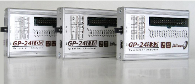
GP-241xx is a USB 2.0 high speed digital pattern generator, logic analyzer
and bi-directional protocol (SPI/I2C) host adapter.
GP-241xx Overview
Byte Paradigm GP-241xx devices are set of a high-speed programmable
bidirectional interfaces that allows the stimulation and the analysis of
digital electronic systems.
Connected to a PC through a USB 2.0 interface and using a fully programmable
hardware accelerator, GP-241xx devices enable a flexible and powerful access
to electronic system boards and electronic devices under test.
The GP-241xx can be turned into an arbitrary digital pattern generator,
logic analyzer or serial protocol master / analyzer, that fits in 16
-
Actual direction setting for each pin depends of the used mode of
operation
-
The limiting factor is the host computer controlling the GP-24100. 48
MByte/s is the maximum throughput achievable by the USB 2.0 connection
hardware implementation.
-
Informative only – depends on the host PC.
-
Each application requires proper mode of operation. Please contact Byte
Paradigm to check about modes of operation roadmap and availability.
-
Actually, the USB 2.0 high speed connection throughput is 60 MB/s (480
Mb/s); this bandwidth must be shared between the data and the USB
protocol controls.
-
Result of a performance test with a Pentium 4 3GHz PC, GP-24100
configured as a pattern generator
| Device |
Data /
Pattern Width |
Maximum
Frequency |
Embedded
Memory |
| GP-24100 |
16 bits |
100 MHz |
8 MByte |
| GP-24116 |
16 bits |
100 MHz |
16 MByte |
|
GP-24132 |
16 bits |
100 MHz |
32 Mbyte |
GP-241xx devices are able to sustain a continuous throughput of 48
MByte/s5. The actual throughput for continuous transfer depends on the host
PC performances and can be expected between 11 MByte/s and 30 MByte/s6. For
most usages – and only for 3.3V I/O standards –GP-241xx device is powered
directly through the host PC USB connection, enabling a very quick device
setup. Additionally, an external power supply can be connected to the
GP-241xx devices when higher current must be sinked through the system or
when another I/O voltage is required.
Minimum Host PC requirements
GP-241xx connects to any PC using Microsoft Windows XP / Windows Vista /
Windows 7 operating systems through a USB 2.0 port connector.
Operating power
The main power supply of the GP-241xx is taken from the USB bus to provide
the necessary voltage to the device core. The system interface can be
powered either from the USB bus (internal power supply mode), either from an
external power supply, to control the voltage level used by the device I/Os
connected to a system under test.
When the internal power supply mode is selected, the GP-241xx is fully
bus-powered and operates without any external power supply. In this mode,
the voltage level of the system interface is fixed to +3.3V (Refer to
section “5 DC and Switching Characteristics” for more details on the
compatible I/O voltage levels for the system connector).
The system connector can however operate at different voltage level between
+1.8V and +3.3V.
An external power supply connector is located at the side of the device. It
is protected with a jumper. This power connector is labeled “GND VEXT”.
Respect the connector polarity
during usage!
An internal automatic switching mechanism holds the I/O voltage between 1.2V
and 3.3V: when the supplied external I/O voltage drops below 1.2V or rises
over 3.3V, the I/O voltage is automatically switched to the internal 3.3V
voltage. This mechanism is not a full voltage protection: the user MUST
respect the absolute maximum ratings, as specified at section 5.1.
Enabling the external power mode:
-
Disconnect the device from the USB bus
-
Remove the jumper from the VEXT connector
-
Connect and apply the external power supply to the VEXT pins of the
system connector (respect
the polarity, as shown on
the label near the connector !)
-
Connect the device to the USB bus.
Enabling the internal power mode (bus powered)::
-
Disconnect the device from the USB bus
-
Shut down and disconnect the external power supply.
-
Connect the device to the USB bus.
USB and system interface connections
A
1.5 or 2 meters USB mini-B to USB type A is provided with all GP-241xx
packages.
A
set of 34 flying lead wires connect the GP-241xx device to the board under
test. A standard pin header with 2.54 mm (0.1 inch) pitch must be foreseen
on the target board where access is desired.
Hardware accelerator configuration
As multi-mode / multi-function device, GP-241xx is mode of
operation-oriented.
The modes of operation currently available7 are:
-
ADWG : digital pattern generator;
-
Analyzer : logic analyzer;
-
SPI : SPI (serial peripheral interface) master and analyzer;
-
I2C : I2C protocol master and analyzer
When used with the 8PI Control Panel software suite, each mode of operation
defines a set of functionalities and configures the GP-241xx device for
proper operation.
Among others, each mode of operation defines:
-
the pins used on the system connector and their direction (in, out or
bi-directional)
-
the ability to use some control features such as repetitive sequences or
triggers
-
the limits to some parameters, such as the maximum clock frequency.
Please refer to 8PI Control Panel user’s guide for more information about
each mode of operation.
Hot plug and play
The GP-241xx USB device can be attached and removed from the host computer
without having to power-down or reboot. There is a delay after connecting
the device to the host system before it is actually functional and reported
as one of the Windows devices; during this time, the host software detects
the GP-241xx and programs its hardware settings.
|
Additional resources |
|
|
Do you prefer
a single application device with the same form factor and performance level? Check: |
|
Wave Generator Xpress : Digital
Pattern Generator
|

|
|
SPI
Xpress : SPI host adapter |

|
|
I2C
Xpress : I2C host adapter
|

|
|