|
Part No: MPDG-Generation-II-Fiber-Optic-CAN-Bridge
Fiber optic converters that electrically isolate signals from the vehicle bus using common bridge and satellite modules interconnected with fiber optic cable for EMI and EMC testing.
Differentiation
Interchangeable bridge modules with built-in functionality for:
- High and Low Speed CAN (HS CAN, LS CAN)
- Single Wire CAN (SW CAN)
- CAN FD
Key Features and Protocols
High Speed CAN with CAN FD Support
- High speed CAN to 1 M bps
- ISO 11898 physical layer
- Terminating resistor options via rotary switch
- None
- 120 Ohm
- Split 120 ohm
- ISO15765 AC termination
Hardware Specifications
- Physical Demensions:
6.5" x 4.125" x 1.5"
- Weight:
12.6 oz
- Operating Range:
-10°C to 80°C
- Electrical:
8-18 VDC
Ease of Use
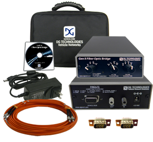
The new Gen II CAN Fiber Optic Bridge offers a simplistic approach for EMI/EMC testing using fiber optic signal communication.
All necessary components for connecting data monitoring equipment to a vehicle bus are included in the kit.
Connection Process

- Place the local and remote bridge modules into position
(EMC chamber/monitoring equipment)
- Connect the bridges together using the fiber optic cable provided
- Set the bridge modules for proper termination and protocol
- Connect the vehicle bus to the remote module using the high density 15 pin D connector.
- Connect the monitoring equipment to the bridge module using the high density 15 pin D connector.
- Begin EMI testing initiatives.
Benefits
- Transmits signals between a Device Under Test (DUT) and monitoring equipment
- Provides optical isolation of vehicle networks during EMI/EMC testing
- Compatible with all CAN protocols
- Quick and easy set up with user friendly controls
- Only requires two fibers between bridge and satellite module
- Exceeds or meets automotive EMC testing specifications
- Radiated emissions
- Bulk current Injection
- Radiated susceptibility
- Rechargeable batteries provide minimum 12 hours of operating time before requiring recharge
CAN FD Support
- Supports the new high speed CAN standard from Bosch
- High speed CAN arbitration phase to 1 M bps
- Data Phase to 5 M bps
Single Wire CAN Support
- Normal and High speed modes
- With or without tool termination resistor
- Fully compliant to GMW3089 V2.4 and J2411 Single Wire CAN specification for Class B in-vehicle communications
- Accurate pass-thru of High Voltage Wakeup signals at Normal bus speeds
Meets Radiated Susceptibility Specifications
The radiated susceptibility of our hardware is to 600 V/meter, reverb and 100 dB (uA), B.C.I.
Requirement levels for the immunity to electromagnetic fields for component and subsystems measured in the anechoic chamber DUT functiona may only deviate above the levels according to the table:

Meets Radiated Emmission Specifications

Meets Bulk Current Injection Specifications
Requirement levels for the immunity to electromagnetic fields for components and subsystems measured using the CBCI and DBCI method.

|